Views: 0 Author: Site Editor Publish Time: 2026-10-18 Origin: Site

A single fluid conveyance failure in heavy machinery rarely ends with just a puddle of oil. In dynamic industrial environments, a ruptured line can trigger catastrophic equipment drops, inject highly toxic fluids into operators, and halt entire production lines. This translates directly to thousands of dollars in unscheduled downtime. The fluid power system acts as the absolute lifeblood of your equipment. Its integrity relies entirely on proper component specification.
Despite these high stakes, procurement managers and maintenance technicians frequently find themselves overwhelmed. The complex matrix of pressure ratings, regional manufacturing standards, and nuanced environmental factors can be difficult to navigate. Without a structured engineering approach, selecting a replacement part often devolves into dangerous guesswork.
This comprehensive guide demystifies complex technical specifications and compares global manufacturing benchmarks. By understanding the underlying physics of fluid power and adhering to established industry frameworks, operators can confidently select the exact components required. This precision maximizes machinery uptime, protects your workforce, and secures a higher return on capital investments.
Continuous vs. Destructive Metrics: Always size your system based on the maximum continuous operating limits. Keep the industry-standard 4:1 safety factor in mind strictly as an emergency buffer, never as an operational target.
Structural Differences Matter: Recognizing the engineering gap between traditional North American specifications and heavy-duty European EN/DIN standards is critical for high-impulse applications.
The Shift to Constant Pressure: Modern fleet management increasingly relies on constant-pressure solutions. This ensures easier routing, simplified inventory, and consistent performance across all inner diameters.
Environmental Realities: System output is merely one variable. Ambient temperature extremes, chemical compatibility, and mechanical routing stress ultimately dictate the true operational lifespan of your assembly.
Objective Purchasing: Implementing the foolproof STAMPED framework guarantees data-backed, objective purchasing decisions every single time.
Before diving into complex technical charts, we must establish a baseline understanding of fluid conveyance architecture. Unlike standard industrial tubing, these components are highly engineered, multi-layered pressure vessels. They are specifically designed to transmit mechanical force under extreme conditions.
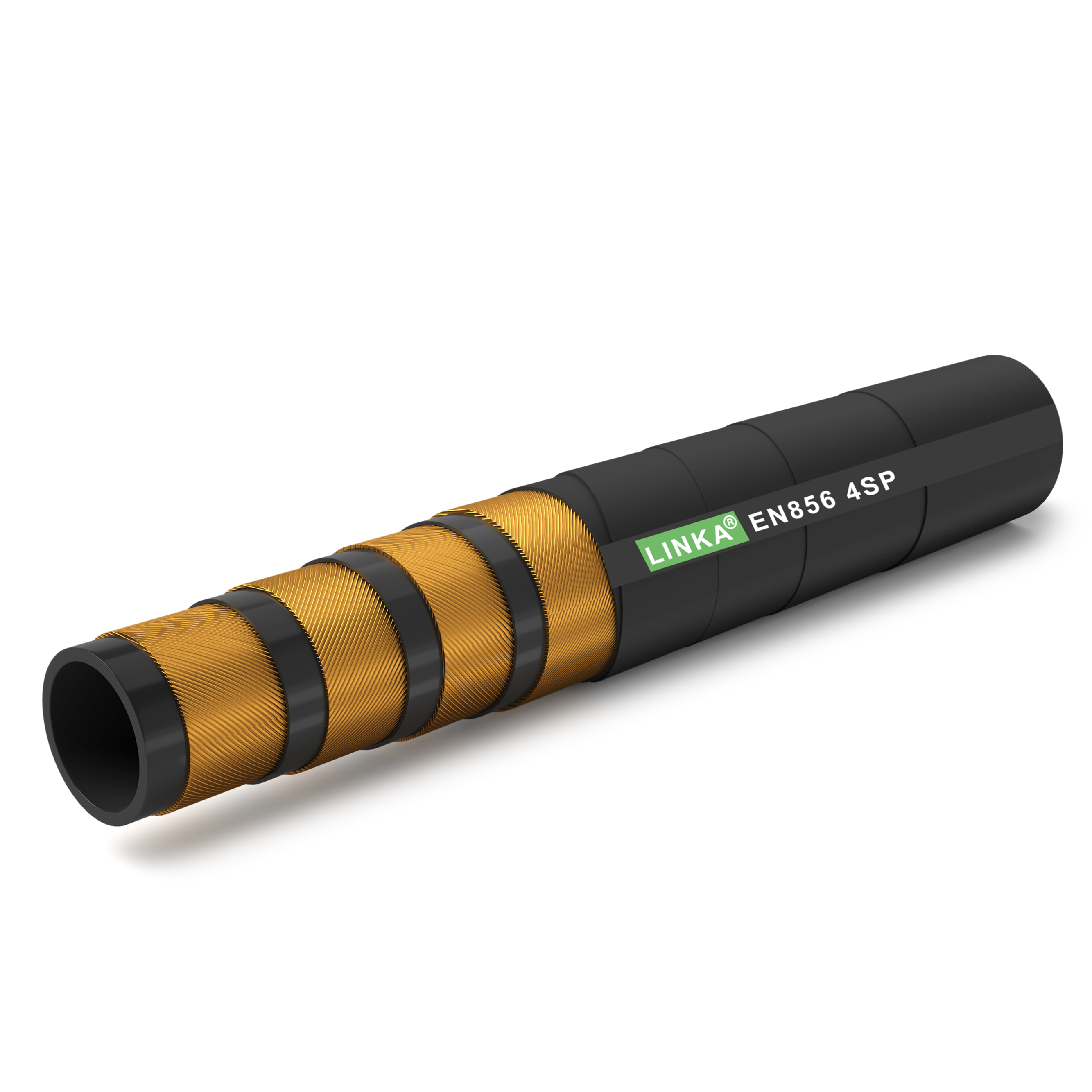
To withstand immense internal forces, a standard assembly is constructed using three primary layers. The inner tube, typically composed of specialized synthetic elastomers like nitrile, must resist chemical degradation from the fluids it carries. Wrapping this tube is the reinforcement layer. This is usually braided or spiraled high-tensile steel wire, serving as the structural backbone. Finally, a durable synthetic outer cover shields the internal wire from environmental hazards like jagged rocks, ozone exposure, and ultraviolet degradation.
Selecting an inadequate pressure rating is a massive financial and safety liability. When an assembly is rated lower than the machine's output, the internal steel wire stretches beyond its yield point and fatigues rapidly. In practical terms, a pinhole leak under high pressure can slice through heavy leather gloves like a scalpel. For operators and fleet managers, mastering these ratings directly translates to lower preventative maintenance costs, reduced fluid replacement expenses, and a drastically safer work environment.
One of the most dangerous errors in system maintenance is misinterpreting pressure metrics. Confusing continuous operating limits with laboratory failure points inevitably leads to premature mechanical breakdowns. From an engineering standpoint, these two numbers serve entirely different purposes.
The working pressure is the absolute maximum continuous internal force the assembly is engineered to handle safely during everyday operations. When evaluating a manufacturer catalog, this is the most critical number to identify. Your machinery's maximum system output, including the relief valve settings, must never exceed this stated limit. Operating even slightly above this threshold accelerates metal fatigue in the reinforcement wires. Over time, this microscopic damage compounds, drastically reducing the component lifespan and voiding any manufacturer warranties.
Conversely, the burst pressure represents a destructive testing metric. It is the absolute maximum force an assembly can withstand in a controlled laboratory environment before its structural integrity completely fails and ruptures.
The fluid power industry universally relies on a strict 4:1 safety factor for standard applications. This means the failure point is engineered to be exactly four times higher than the continuous operating limit. For instance, if a component is rated for 3,000 PSI, it has survived laboratory tests up to 12,000 PSI. This massive buffer exists solely to protect operators from unpredictable systemic anomalies. You should never intentionally push a system anywhere near this destructive limit.
Industrial machinery rarely operates in a static state. These are highly dynamic environments prone to sudden mechanical shocks. When heavy loads are suddenly dropped or directional valves slam shut, the system experiences a violent pressure spike, commonly referred to as the water hammer effect. These micro-second surges can easily push internal forces well beyond the normal operating output. Engineers must account for dynamic environments by selecting a rating that comfortably accommodates these temporary spikes without eating into the critical safety margin.
Securing the correct replacement part requires matching the component to regional or original equipment manufacturer requirements. Navigating global manufacturing standards ensures secure fittings, proper flow rates, and overall operational safety.
The Society of Automotive Engineers established the foundational J517 standard, which remains a dominant benchmark in North American manufacturing. The traditional SAE 100R hydraulic hose series covers a broad spectrum of construction types, ranging from single-wire braided designs to multi-wire configurations. Take the standard SAE 100R2AT specification as an example. A defining characteristic of these traditional standards is that the pressure capability typically decreases as the inside diameter increases. A quarter-inch line might handle 5,800 PSI, but a one-inch line of the exact same specification drops significantly to 2,400 PSI. This variable scale requires procurement officers to meticulously check sizing charts for every individual replacement.
For extreme heavy-duty applications, the European EN 856 and DIN standards are widely preferred. This standard governs the construction of the 4SP 4SH spiral hose, which abandons traditional woven braids in favor of four layers of high-tensile steel wire wrapped in alternating spiral directions. This advanced spiral construction minimizes internal wire friction during aggressive pressure pulses. Because the wires glide rather than rub against each other, these lines easily handle continuous pressures exceeding 6,000 PSI. They are the definitive choice for ultra-high-pressure, high-impulse machinery like mining excavators, hydrostatic drives, and large-scale earthmoving equipment.
To streamline engineering and inventory management, the fluid power sector has heavily embraced ISO 18752 standards. This modern framework classifies components by performance and pressure capabilities rather than specific construction methods. The modern R19 hydraulic hose perfectly exemplifies this evolution. Its primary engineering triumph is maintaining the exact same maximum operating limit regardless of the inner diameter. Whether you are routing a compact quarter-inch pilot line or a massive one-inch main return line, the 4,000 PSI rating remains constant. This drastically simplifies the selection process and reduces the risk of dangerous installation errors.
| Standard Type | Typical Construction | Pressure Profile | Ideal Application |
|---|---|---|---|
| SAE 100R Series | 1 to 2-wire braided steel | Variable. Pressure drops as diameter increases. | General industrial equipment, agriculture, standard fluid power systems. |
| EN 856 4SP / 4SH | 4-wire alternating spiral steel | Ultra-high pressure. Exceptional impulse resistance. | Heavy construction, mining excavators, high-shock hydrostatic drives. |
| ISO 18752 / R19 | Braided or spiral depending on size | Constant pressure across all inner diameters. | Modern fleet management, compact routing, simplified inventory control. |
Looking at the broader fluid power landscape, equipment manufacturers are consistently pushing for higher power density. Modern machinery is becoming more compact, requiring hydraulic systems to deliver immense force within incredibly tight physical footprints. This trend forces fluid conveyance components to handle unprecedented pressure levels without increasing their outer diameters. Thicker lines would simply fail to route through the narrow machine chassis of modern skid steers and compact excavators.
Furthermore, the industry is witnessing a significant shift toward environmentally acceptable lubricants and synthetic hydraulic fluids. While these fluids protect the environment in the event of a spill, they can be highly aggressive toward traditional rubber compounds. As a result, polymer chemists are developing highly advanced inner tube materials. By utilizing specialized thermoplastic and synthetic rubber blends, modern lines offer superior chemical resistance while maintaining flexibility in extreme temperatures.
While structural strength dictates a component's maximum capacity, the surrounding environment dictates its actual survival rate. Ignoring operational realities will lead to premature failure, regardless of how robust the initial specifications appear on paper.
Thermal stress attacks fluid systems on two distinct fronts. Picture a heavy wheel loader operating in a sun-baked rock quarry. The external jacket is subjected to intense ambient heat and direct UV rays, while the internal tube is simultaneously battered by scalding hydraulic oil. Extreme heat causes elastomeric polymers to cure prematurely, leading to hardening, cracking, and eventual leaks. Conversely, sub-zero winter operations cause standard rubber to become brittle. This drastically increases the likelihood of the cover shattering when the machine articulates.
The inner tube material must be scientifically matched to the specific fluid coursing through the system. Industrial equipment utilizes various mediums, including standard petroleum-based oils, synthetic fire-resistant fluids, and water-glycol mixtures. If an incompatible fluid is introduced, the inner tube will rapidly degrade, swell, or dissolve. This chemical breakdown not only destroys the line itself but also flushes abrasive rubber particulates directly into expensive pumps and precision valves.
Every manufactured line features a strict minimum bend radius. This is the tightest arc it can achieve without suffering structural compromise. When a line is bent tighter than its designated rating, the outer curve of the wire reinforcement stretches dangerously thin, while the inner curve is crushed. This mechanical distortion restricts fluid flow, generates excess heat through friction, and creates a highly localized weak point prone to violent blowouts.
To eliminate guesswork and ensure precise component selection, industry professionals rely on the STAMPED framework. Applying this standardized checklist guarantees that all operational variables are addressed prior to assembly.
Size: Measure the inner diameter for proper fluid velocity, the outer diameter to ensure routing clearance, and the exact overall length of the assembly.
Temperature: Identify both the maximum internal fluid heat and the ambient environmental extremes the machinery will face.
Application: Define the working environment. Will the assembly face severe physical abrasion, constant flexing, or tight routing angles?
Material: Verify that the inner tube compound is completely chemically compatible with the system's specific hydraulic fluid.
Pressure: Ensure the continuous operating limit equals or exceeds the maximum system output, accounting for dynamic surge spikes.
Ends: Select the appropriate steel couplings, thread types like NPT, JIC, or ORFS, and sealing methods to guarantee a leak-free mechanical connection.
Delivery: Determine specific testing requirements like proof testing, packaging standards, and delivery timelines necessary to keep your facility running.
Implementing a rigorous preventative maintenance schedule is the most effective defense against catastrophic equipment failure. Fleet managers must train their technicians to identify subtle indicators of metal and rubber fatigue.
High-pressure lines rarely burst without offering warning signs. Routine visual audits should actively look for severe cover abrasion. If the outer rubber is rubbed away and the steel reinforcement is exposed, ambient moisture will quickly rust the wire, destroying its tensile strength. Additionally, localized ballooning or blistering on the jacket indicates that the inner tube has already ruptured, allowing fluid to leak into the reinforcement layer. Finally, any weeping or oil pooling around the crimped ends suggests the mechanical seal has degraded and requires immediate replacement.
High-utilization machinery should undergo visual inspections daily, supplemented by comprehensive mechanical audits every few hundred operating hours. In highly abrasive environments like forestry or mining, operators should proactively install protective accessories. Nylon abrasion sleeves, steel spiral guards, or silicone fire sleeves drastically mitigate external damage. Importantly, safety standards dictate that technicians must never mix and match hoses and fittings from different manufacturers. Mismatched crimp tolerances inevitably lead to dangerous blow-offs.
Selecting the correct fluid conveyance component is a precise engineering discipline. You must carefully balance continuous operating limits against globally recognized manufacturing standards. Because harsh industrial environments will ruthlessly test your equipment daily, ignoring established frameworks like the STAMPED method inevitably leads to dangerous and financially devastating machine failures.
Never cut corners on these critical ratings. Take the time to audit your current hydraulic systems, identify signs of wear, and prioritize certified, high-grade components over low-cost alternatives. Ready to upgrade your fluid power system? Stop relying on guesswork and secure the long-term operational stability your workforce deserves. Evaluate your machinery requirements today and source the exact engineered specifications you need at HoseBiz to keep your production lines moving safely and efficiently.
Absolutely not. This metric is strictly a laboratory failure point used to establish an emergency safety margin. To ensure operator safety and component longevity, you must only operate the system at or below the manufacturer's stated continuous operating limit.
Selecting an inner diameter that is too small restricts fluid flow, which causes severe pressure drops, generates excessive systemic heat, and forces your pumps to work harder, leading to premature mechanical failure. Conversely, a diameter that is too large reduces fluid velocity, causing sluggish machine response times and creating unnecessary routing difficulties due to the bulky outer diameter.
The SAE 100R series covers a broad range of braided and spiral constructions where the pressure capacity often decreases as the line gets wider. In contrast, EN 4SP and 4SH specifications are specifically engineered with a heavy-duty four-wire spiral construction. They are designed explicitly to handle the ultra-high-pressure, high-impulse environments commonly found in heavy industrial machinery.
Unlike traditional designs where pressure ratings drop as the diameter increases, the R19 specification provides the exact same maximum operating limit across all inner diameter sizes. This uniform rating greatly simplifies the engineering selection process and streamlines replacement inventory for large fleets.
Exceeding the maximum rated temperature softens the elastomeric inner tube and outer cover, which drastically reduces the structural integrity of the entire assembly. When operating at extreme temperatures, the effective working pressure capacity of the line decreases, meaning a pressure spike that is normally safe could easily cause a blowout in an overheated system.
A pressure drop occurs due to internal fluid friction as oil travels through the assembly. If the inner diameter is too narrow or the routing is excessively long, the machine loses mechanical efficiency. The system is then forced to consume more energy to perform the same task, which generates excess heat and accelerates component wear.
Replacement intervals depend heavily on specific working conditions, including pressure cycle frequency, UV exposure, and thermal extremes. However, most industrial preventative maintenance schedules recommend replacing high-use assemblies every one to two years, or immediately if any visual damage, abrasion, or leakage is detected during routine inspections.


