Views: 0 Author: Site Editor Publish Time: 2026-10-14 Origin: Site

Installing the wrong hose is a guaranteed way to trigger a dangerous blowout on the factory floor. I have seen mismatched parts destroy expensive machinery and create severe safety hazards. Unmatched components do not just cause minor leaks. They lead to catastrophic system failures and massive downtime. High-pressure machines face extreme mechanical stress and environmental abuse every single day. This reality makes finding exact component specifications a daunting challenge for procurement teams and engineers.
In this technical guide, you will learn the exact methodologies used by fluid power professionals. We will discuss how to evaluate specifications, decode complex industry standards, and ultimately choose a reliable high pressure hydraulic hose safely and effectively.
Pressure is Paramount: Always select a component where the maximum working pressure strictly meets or exceeds your system peak pressure. You must account for sudden pressure spikes during operation.
Know Your Standards: Understanding the distinct differences between American and European manufacturing norms is crucial for exact replacements.
Use the STAMPED Method: Size, Temperature, Application, Material, Pressure, Ends, and Delivery represent the seven non-negotiable factors for accurate selection.
Fittings Matter as Much as the Hose: A premium-quality assembly will inevitably fail if paired with incompatible or improperly crimped end fittings.
Supplier Reliability is Key: Partnering with a manufacturer who conducts rigorous burst and impulse testing ensures long-term operational safety.
You must first understand what separates standard fluid transfer tubes from heavy-duty variants. Utility lines handle low-pressure water or basic shop pneumatics. In contrast, industrial hydraulic lines are engineered to withstand immense internal forces. These forces often exceed 3,000 to 6,000 PSI. Simultaneously, these lines endure harsh external environments. They serve as the critical lifelines in excavators, industrial presses, and heavy agricultural machinery.
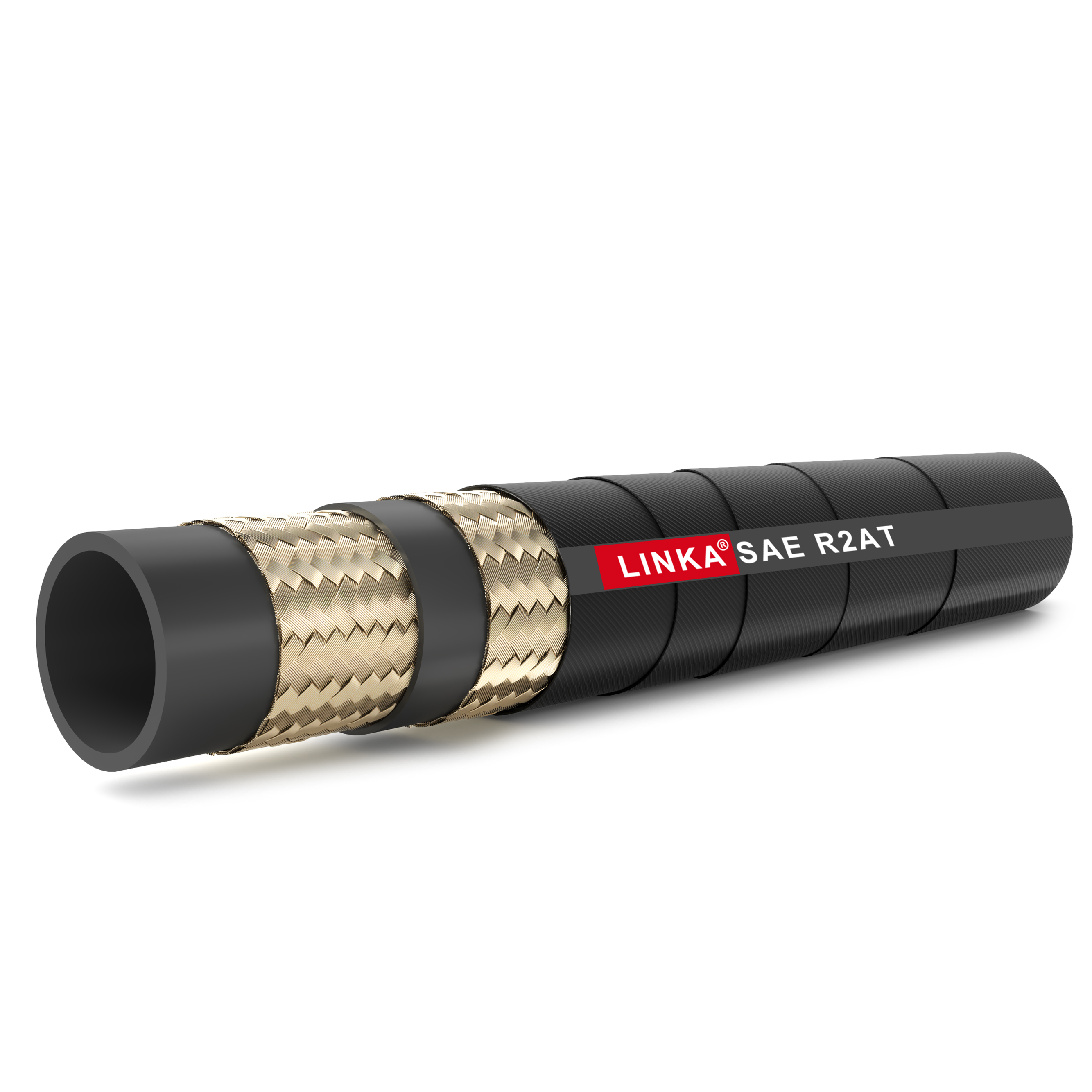
These components rely entirely on a highly engineered, three-layer construction model. This structure guarantees durability and pressure resistance. Each layer serves a distinct, non-interchangeable purpose in the field.
The Inner Tube: Serving as the innermost boundary, this layer comes into direct contact with the fluid. It must possess absolute chemical compatibility with the specific media being transferred. Typical materials include synthetic elastomers like Nitrile NBR. A high-quality NBR tube prevents fluid degradation and seepage.
The Reinforcement Layer: This is the structural core responsible for the pressure-holding capability. Without this metallic skeleton, the inner tube would rupture instantly under load. It consists of high-tensile steel wire woven or wrapped tightly around the inner tube.
The Outer Cover: Functioning as the primary defense against the elements, this exterior layer protects the internal structure. A standard rubber hydraulic hose typically utilizes synthetic compounds like Neoprene CR or Styrene-Butadiene Rubber SBR. These materials provide a vital balance of flexibility, UV resistance, and abrasion protection.
The specific geometry of the reinforcement layer dictates both the maximum working pressure and the physical flexibility of the assembly. Industry standards divide this reinforcement into two primary categories. These are wire braid and wire spiral.
Braided reinforcement involves weaving steel wires in a crisscross, overlapping pattern. This design allows for excellent flexibility and a tighter bending radius. Therefore, it is ideal for medium to high-pressure applications where routing space within the machine chassis is severely limited. On the other hand, spiral reinforcement consists of parallel wires wrapped in alternating, stacked layers. This heavy-duty construction minimizes wire friction during violent pressure surges. It is the required standard for extreme high-pressure and high-impulse applications.
To make the selection process clearer, review the core differences below.
| Feature | Wire Braid Construction | Wire Spiral Construction |
|---|---|---|
| Wire Arrangement | Crisscross woven pattern | Parallel wires in stacked layers |
| Flexibility | High flexibility, tight bend radius | Stiffer, larger minimum bend radius |
| Pressure Capacity | Medium to High up to 5,800 PSI | Extreme High up to 10,000+ PSI |
| Impulse Resistance | Standard impulse life | Superior resistance to violent surges |
| Best Application | Forklifts, tractors, compact routing | Heavy excavators, mining equipment |
Furthermore, recent market data highlights a massive shift toward compact heavy machinery. Modern excavators pack more hydraulic power into tighter frames. This trend forces engineers to abandon bulky legacy designs. Instead, the industry is moving toward high-impulse, ultra-flexible spiral hoses. These advanced lines can handle severe pressure spikes while safely navigating cramped engine compartments.
Navigating the technical jargon on specification sheets is a notorious hurdle for procurement teams. Fluid power systems rely on standardized manufacturing norms to ensure global compatibility and safety. The two most prevalent systems dictating these rules are the American SAE Society of Automotive Engineers and the European EN European Norm standards.
The SAE J517 guidelines dictate the strict manufacturing requirements, pressure ratings, and dimensional tolerances for fluid power components in North America. Within this framework, the SAE 100R series is the most widely referenced benchmark. Each designation specifies a unique construction type. Adhering to an SAE hydraulic hose standard ensures the component has undergone rigorous testing. This allows for safe, plug-and-play integration into existing machinery.
When reviewing replacement parts, buyers frequently encounter overlapping terminology. Clarifying these nuances is critical to avoiding dangerous specification errors on the shop floor.
The terms 1SN 2SN hydraulic hose refer directly to the European EN 853 standard. The numerical values denote the exact number of high-tensile steel wire braid layers. The SN suffix indicates that the component features a no-skive design.
Conversely, the R1AT and R2AT designations refer to the SAE 100R1 and 100R2 standards. Similar to the European naming convention, the numbers indicate one or two layers of wire braid. The AT designates a no-skive construction. Specifically, a standard two-wire R2AT assembly typically features an NBR inner tube and operates safely in temperatures ranging from -40 degrees to +100 degrees Celsius. While these two standards are structurally similar, the EN 853 standard generally requires slightly higher working pressure ratings at specific diameters compared to the baseline SAE standard.
The no-skive feature represents a massive leap in assembly efficiency. Historically, technicians had to physically shave off a portion of the outer rubber cover. This allowed the metal fitting to bite directly into the wire reinforcement. No-skive designs feature a precisely engineered outer cover thickness. Compatible fittings can crimp directly through the rubber. This eliminates the messy skiving process and drastically reduces the risk of damaging the wire braid.
Selecting the correct component requires a highly systematic approach. Guesswork leads to catastrophic field failures. The fluid power industry universally relies on the STAMPED framework. This is a rigorous, seven-step evaluation process.
Size is the foundational metric of fluid power. It encompasses the inner diameter, outer diameter, and overall assembly length. The inner diameter is particularly critical. It must be precisely sized to maintain proper fluid velocity. If the inner diameter is too small, fluid velocity skyrockets. This restriction generates excessive friction and ultimately cripples system efficiency. Engineers utilize a specialized nomograph chart to calculate the exact required inner diameter based on flow rate.
Temperature evaluation must account for two distinct environments. You must check the internal media temperature and the external ambient conditions. Continuous operation above the rated maximum temperature will rapidly bake the synthetic rubber inner tube. This leads to brittleness and cracking. Imagine a machine experiencing a harsh winter cold-start. If the rubber is not rated for sub-zero ambient temperatures, the stiffened material can fracture the moment the system pressurizes.
Application encompasses the physical reality the assembly will endure. Will the equipment operate in a high-abrasion environment like a granite quarry? Will it face continuous ultraviolet light or corrosive chemical washdowns? You must also consider whether the component will be subjected to continuous robotic flexing or a static installation. Specialized outer covers are often required to survive these harsh variables.
The inner tube material must be chemically compatible with the specific fluid utilized in the system. Common fluids include petroleum-based oils, synthetic lubricants, and water-glycol fire-resistant fluids. Introducing an incompatible fluid will cause the inner tube to swell or dissolve entirely. This destroys the rubber and sends debris straight into the system's expensive pumps. Always verify compatibility using a chemical resistance chart.
Pressure is a strict safety metric. The maximum working pressure of the selected assembly must equal or exceed the maximum system pressure. You must explicitly include any potential pressure spikes. Industry standards mandate a strict 4:1 safety factor for standard applications. This means the theoretical burst pressure must be at least four times the stated maximum working pressure. This provides a critical safety margin against metal fatigue.
A hydraulic assembly is only as robust as its connection points. The Ends refer to the specific metallic fittings required to interface with the machinery. This involves identifying the correct thread type, the sealing mechanism, and the physical orientation. A straight fitting performs very differently than a 90-degree swept elbow under high flow.
Delivery refers to the volume of fluid that must pass through the system and the velocity at which it travels. This factor ties closely back to the Size parameter. Ensuring proper delivery prevents pump cavitation. Cavitation is a destructive phenomenon where vapor bubbles implode against metal surfaces. Proper delivery maintains the necessary mechanical force required by the actuators.
Selecting the correct flexible line is only half the engineering challenge. The tube and its end fittings must be evaluated as a single, cohesive pressure-containment system. A premium line will still experience catastrophic failure if paired with incompatible or poorly machined ends.
The industrial sector utilizes several standardized thread types and sealing methods. Understanding these mechanical differences is essential for preventing leaks.
NPT National Pipe Tapered: Common in older North American equipment, this fitting relies on thread deformation to create a seal. It is less ideal for extreme high-pressure or high-vibration systems.
JIC Joint Industry Council 37-degree Flare: Uses a flared seating surface to create a highly reliable metal-to-metal seal. It is exceptionally common due to its reusability and resistance to high temperatures.
ORFS O-Ring Face Seal: Features a flat face with an embedded elastomeric O-ring that compresses against a mating surface. This design offers superior leak resistance in high-vibration environments.
BSP British Standard Pipe: Widely used in European and Asian machinery. Identifying the exact thread pitch is vital to prevent stripping during installation.
A highly dangerous practice in maintenance facilities is mixing lines from one manufacturer with fittings from another. Two components may appear visually compatible on paper. However, microscopic manufacturing tolerances vary significantly between brands.
When a fitting is crimped, the metal shell must compress the rubber cover and bite into the wire reinforcement at a highly precise diameter. If the fitting is not explicitly engineered for that specific wall thickness, the crimp will fail. This mismatch frequently leads to fitting blow-offs. A blown fitting under 5,000 PSI can cause a fluid injection injury. This is a severe medical emergency where oil is shot directly through an operator's skin. Always utilize fittings that are tested and explicitly approved by the manufacturer.
Procurement teams must frequently decide between standard assemblies and custom-fabricated solutions. The correct choice depends entirely on the operational context.
Standard assemblies are manufactured to predefined lengths and fitting configurations. They are highly suitable for routine maintenance schedules where OEM specifications align perfectly with market offerings. Utilizing standard assemblies reduces lead times and simplifies inventory management for equipment fleets.
Custom-made assemblies become absolute necessities when dealing with highly specialized equipment. Custom fabrication allows engineers to specify non-standard lengths to prevent excessive slack from snagging on moving parts. Furthermore, custom builds allow for specific fitting orientations to navigate tight engine compartments. For heavy industry, the slightly higher initial cost of a custom assembly is vastly outweighed by the prevention of costly facility downtime.
Proper installation and routing are just as critical as the initial selection process. Even the highest quality component will fail prematurely if subjected to improper mechanical stress.
The minimum bend radius is a strict manufacturer specification. It defines the tightest arc the component can achieve without sustaining internal structural damage. If an assembly is forced into a bend tighter than its rated limit, severe wire fatigue occurs. The metal reinforcement layers on the outside of the bend stretch beyond their yield point. Meanwhile, the wires on the inside compress and buckle. This causes the inner tube to kink, restricting fluid flow and inevitably leading to a blowout.
To maximize operational lifespan, installation technicians must adhere to established routing principles. First, never twist the assembly during installation. Even a slight 7-degree twist can reduce the component's lifespan by up to 90 percent. Technicians should always employ a two-wrench method during installation. One wrench anchors the line to prevent rotation, while the other torques the fitting to spec. Additionally, hydraulic lines can contract in length by up to 4 percent when pressurized. Routing must include sufficient slack to accommodate this dimensional change.
For procurement managers, vetting the manufacturer is a critical risk-management exercise. The quality of the final product is directly tied to the supplier's engineering infrastructure.
A reputable supplier must operate under strict, verifiable quality management systems. Buyers should demand proof of ISO 9001 certification. Furthermore, check if the supplier provides detailed test reports for their extreme-duty R1AT R2AT hydraulic hose offerings. This documentation ensures they meet exact dimensional tolerances.
Theoretical pressure ratings on a spec sheet are insufficient for critical industrial applications. Reliable manufacturers maintain in-house testing facilities. Look for suppliers that conduct rigorous impulse testing. This simulates the rapid pressure spikes of real-world operation by subjecting the assembly to hundreds of thousands of pressure cycles. Burst testing is equally vital to guarantee the 4:1 safety factor.
Beyond manufacturing, a strong supplier acts as a technical partner. They should offer robust engineering support, including providing precise crimp specifications for custom assemblies and offering responsive troubleshooting during emergency breakdowns.
Choosing the correct fluid power components ensures machinery safety and eliminates dangerous oil spills. By strictly matching your system pressure to the appropriate rating and utilizing the STAMPED method, you protect both your workforce and your capital equipment. Partnering with a tested supplier guarantees long-term performance.
There is no strict, universal timeline for replacement. The lifespan depends entirely on the operating environment, fluid temperature, and pressure cycling. However, preventive replacement every 1 to 2 years is standard practice for high-stress industrial applications. Maintenance teams should conduct regular visual inspections, looking for stiff covers, exposed wire reinforcement, or weeping fluid around fittings.
No. A standard rubber water or air line is fundamentally unsuited for hydraulic systems. It lacks the high-tensile steel wire reinforcement required to contain extreme pressure. Additionally, standard rubber degrades rapidly when exposed to petroleum-based fluids, leading to internal swelling and inevitable rupture.
Using an underrated component will lead to catastrophic failure. When the system's pressure spikes exceed the structural capacity, it will burst. This causes rapid fluid loss, severe environmental damage, and extensive equipment downtime. More importantly, high-pressure fluid injection injuries can occur, which are severe medical emergencies.
Engineers should look for localized blistering on the outer cover, which indicates fluid has breached the inner tube. Other major warning signs include weeping oil at the crimp fitting, severe abrasion that exposes the steel wire braid, and noticeable stiffening or cracking of the rubber due to heat damage. Any of these signs warrant immediate replacement.
Engineers use a fluid velocity nomograph. You must know the system's flow rate in gallons per minute. For standard pressure lines, fluid velocity should be kept between 10 and 20 feet per second. By plotting the flow rate and target velocity on the nomograph, you can identify the exact inner diameter required to prevent excessive friction and heat generation.
Ready to upgrade your fluid power systems with components engineered for absolute safety and durability? Evaluate your system's exact specifications and source premium, rigorously tested hydraulic solutions directly from Hosebiz today.


