Views: 0 Author: Site Editor Publish Time: 2026-08-20 Origin: Site

High-pressure failures in mobile hydraulic machinery don't just cause downtime. They pose severe safety and environmental risks. Fluid leaks from heavy machinery often lead to soil contamination and costly cleanup efforts. While the SAE J517 standard provides a reliable baseline for fluid power systems, specifying an SAE Hose for mobile equipment requires deeper analysis. You must account for dynamic loads, tight routing, and extreme abrasion. Stationary factory equipment rarely faces these same harsh elements. Selecting the optimal assembly requires moving beyond basic pressure ratings. You need to carefully evaluate construction type, impulse life, and end-fitting compatibility. Doing so prevents sudden line bursts during critical operations. Readers will learn how to assess environmental stressors and decode complex industry specifications. We will also cover practical frameworks for choosing between braided and spiral designs to maximize reliability in the field.
Baseline compliance with a hydraulic hose standard is insufficient for mobile equipment; abrasion resistance and flexibility are equally critical to preventing premature failure.
Matching working pressure to system relief valves is non-negotiable; always account for hydraulic pressure spikes inherent in mobile applications.
The choice between a steel wire braided hose and a spiral hose dictates the balance between spatial flexibility (bend radius) and impulse cycle longevity.
Mixing hose and fitting manufacturers voids warranties and introduces severe safety hazards.
Differentiating between stationary industrial hydraulics and mobile equipment remains critical for proper specification. Stationary systems operate inside climate-controlled facilities. They follow predictable routing paths and face minimal environmental disruption. Mobile machinery changes this equation completely. Excavators, wheel loaders, and agricultural tractors subject their fluid power systems to constant, dynamic stress. A mobile hydraulic hose experiences relentless articulation, vibration, and exposure to the elements.
When engineering fluid lines for mobile fleets, your success criteria must shift. An optimal specification maximizes Mean Time Between Failures (MTBF). You also need to maintain ease of field maintenance and high routing flexibility. If a fluid line fails on a remote construction site, the resulting downtime easily halts an entire project. Field technicians need lines they can easily replace in cramped chassis compartments.
Mobile equipment faces intense environmental stressors rarely seen indoors. Consider these common field hazards when evaluating line replacements:
Constant UV exposure and ozone degradation: Sunlight breaks down standard rubber compounds, causing brittle, cracked outer covers over time.
High-abrasion environments: Lines constantly rub against metal chassis components, jagged rocks, and abrasive debris during operation.
Extreme temperature fluctuations: Mobile fleets endure freezing winter mornings and scorching summer afternoons, altering the physical properties of both the fluid and the rubber assembly.
Ignoring these stressors leads to premature catastrophic failures. You must prioritize environmental ruggedness alongside standard performance metrics.
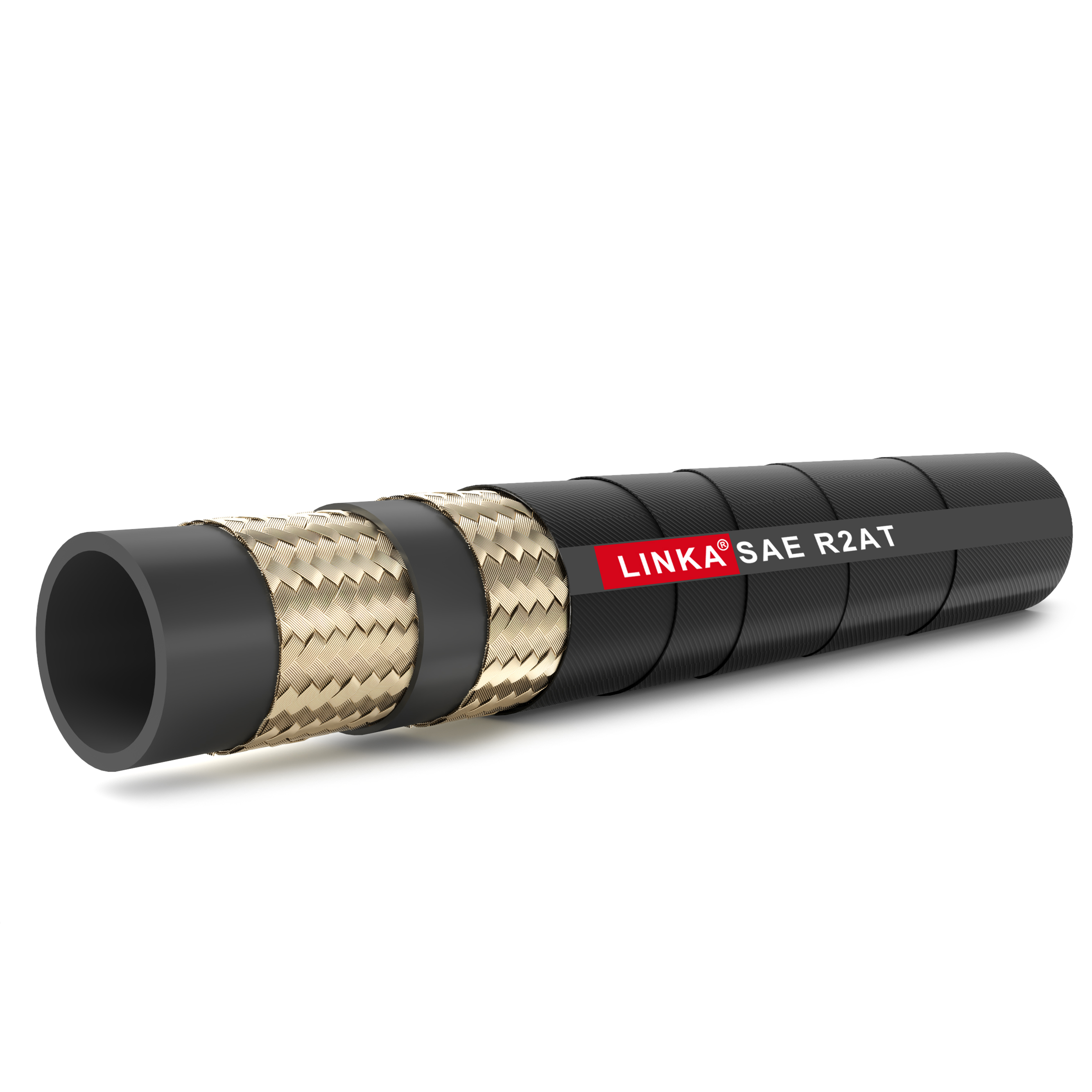
The Society of Automotive Engineers (SAE) established the J517 standard to provide consistent benchmarks for fluid power lines. This standard categorizes products into the 100R-series. While comprehensive, not every 100R specification fits the demanding nature of mobile machinery. You must map these solution categories to the correct application.
Medium-to-high pressure categories include 100R1, 100R2, and 100R16. These options represent the workhorses of general mobile implement circuits. The 100R16 line, in particular, offers smaller outer diameters and tighter bend radii compared to traditional 100R2 lines. Technicians rely on them heavily for auxiliary attachments and steering circuits where space remains highly constrained.
Extreme high-pressure applications demand 100R12, 100R13, or 100R15 specifications. You need these robust designs for hydrostatic transmissions and heavy-duty boom cylinders. Heavy lifting creates massive pressure surges. These specifications utilize multiple layers of spiral-wound wire to deliver exceptional impulse resistance.
Remember a crucial industry reality: SAE standards set the baseline minimums. Many manufacturers produce proprietary products exceeding these baseline requirements. You will frequently see components offering half the minimum bend radius or boasting one million-plus impulse cycles. You should evaluate these premium options based on their performance value and operational return, rather than defaulting to the bare minimum specification.
| SAE Specification | Construction Type | Primary Mobile Application | Key Benefit |
|---|---|---|---|
| 100R1 | 1-Wire Braid | Low-to-Medium Pressure Return Lines | High flexibility and lightweight. |
| 100R2 | 2-Wire Braid | General Implement Circuits | Reliable everyday medium-pressure performance. |
| 100R16 | 2-Wire Braid (Compact) | Tight Routing / Articulation Joints | Half-bend radius capabilities. |
| 100R12 | 4-Wire Spiral | Main System Pressure Lines | Handles severe pressure spikes. |
| 100R15 | 6-Wire Spiral | Hydrostatic Drives / Heavy Boom Lift | Maximum impulse life at extreme pressures. |
Selecting the correct fluid power line requires a structured approach. The industry-standard S.T.A.M.P.E.D. framework ensures you cover every critical variable before finalizing a specification. Applying this method rigorously prevents costly oversight in mobile fleet maintenance.
Sizing involves two critical dimensions. First, you must calculate the correct internal diameter (I.D.). Undersized I.D.s cause high fluid velocity, leading to severe heat generation and system inefficiency. Conversely, you must verify the outer diameter (O.D.). Mobile chassis routing often involves passing lines through incredibly tight bulkheads. A bulky cover can easily cause binding and abrasion.
Mobile machinery experiences two distinct temperature extremes. Ambient temperature refers to the external weather conditions. Internal temperature refers to the hydraulic fluid itself. Standard rubber compounds typically handle internal fluids up to 212°F (100°C). However, modern high-flow mobile systems often push fluids hotter. You must verify both temperature ratings to prevent the inner tube from baking, cracking, or prematurely hardening.
Identify the specific dynamic movements the line will experience. Does it route across a pivotal articulation joint on a wheel loader? Or does it remain static along a rigid boom arm? Applications experiencing constant flexing require tighter bend radii and superior fatigue resistance. You also need to assess external environmental threats like falling debris or intense vibration.
Ensure tube compound compatibility. Fluid formulas change rapidly. Modern fleets increasingly use biodegradable hydraulic fluids to meet environmental regulations. Traditional Nitrile inner tubes may degrade when exposed to certain synthetic or eco-friendly fluids. Always cross-reference the manufacturer's chemical compatibility chart to guarantee the inner material resists breakdown from the chosen fluid.
Average operating pressure tells only half the story. Mobile applications inherently generate massive hydraulic pressure spikes. Dropping a loaded excavator bucket and suddenly stopping it sends a shockwave through the system. You must size your line for the highest system pressure spikes. Match the working pressure rating to the system relief valves, ensuring a comfortable safety margin.
A flawless tube fails instantly if paired with the wrong fitting. You must specify the correct thread and seal type suited for high-vibration mobile environments. O-Ring Face Seal (ORFS) and JIC fittings dominate mobile machinery due to their reliability under stress. Carefully match the fitting configuration to the mating port to prevent weeping leaks over time.
Logistics matter. Factor in lead times for specialized configurations. Standard lines might sit on local distributor shelves, but specialized outer covers require advance planning. If your application demands Ultra-High Molecular Weight Polyethylene (UHMWPE) abrasion-resistant covers, account for potential supply chain delays to avoid keeping a valuable machine offline.
Understanding the internal construction of your fluid lines defines system longevity. Manufacturers primarily use two distinct reinforcement methods: braided wire and spiral wire. Each offers distinct advantages and limitations when applied to mobile machinery.
You evaluate these constructions across several dimensions. Spatial flexibility dictates how easily a technician can bend the line during installation. Impulse cycle longevity dictates how many pressure surges the line can absorb before the reinforcing wire fatigues and snaps.
Braided construction weaves steel wires together in an overlapping crisscross pattern. This design prioritizes physical flexibility.
Pros: Superior flexibility, extremely tight bend radii, and highly cost-effective for general use.
Cons: Lower resistance to extreme pressure spikes. The overlapping wires rub against one another during pressure surges, causing internal friction and eventual fatigue.
Best for: Auxiliary lines, steering circuits, return lines, and medium-pressure implements.
Spiral construction wraps high-tensile steel wires in parallel layers, alternating wrap directions between layers. This design resists expansive forces brilliantly, making it the premier choice for a high pressure hydraulic hose.
Pros: Exceptional impulse life. It handles extreme pressure surges without wire friction fatigue, extending service life dramatically in harsh circuits.
Cons: Highly stiff. It remains incredibly difficult to route in tight spaces, weighs significantly more, and costs more to manufacture.
Best for: Main hydrostatic drives, heavy lifting boom cylinders, and primary pump discharge lines.
Choosing between them requires balancing high impulse ratings against physical constraints. If an application generates frequent pressure spikes exceeding 4,000 PSI, default to a spiral design. However, if that same application requires the line to bend 90 degrees within a six-inch space, a standard spiral option will buckle or apply destructive side-load to the fitting. In such cases, you must look to advanced compact spiral designs or re-engineer the hardline tubing route to accommodate the stiff spiral construction.
Even a perfectly specified component fails prematurely if implemented poorly. The real world of mobile machinery punishes sloppy installation. Proper engineering requires anticipating how the line behaves once pressurized.
A correctly specified line will still fail if routed poorly. Pressurized lines shrink in length by up to 4%. If technicians install lines perfectly tight between two ports, pressurization will tear the fittings right off the crimp. You must allow slack. Furthermore, twisting a line just five degrees during installation reduces its operational lifespan by 70%. Technicians must use the layline—the printed text running along the cover—as a visual guide to ensure the assembly remains untwisted.
The "Mix and Match" hazard represents a critical safety failure in the industry. Many maintenance shops attempt to pair a line from Manufacturer A with fittings from Manufacturer B. This compromises the crimp integrity. Manufacturers engineer their fittings to bite into their specific rubber compounds at precise micrometer tolerances. Mixing brands voids warranties and introduces severe safety hazards, risking high-velocity fluid injection injuries if the fitting blows off.
Abrasion mitigation extends life drastically. You must decide when to rely on standard rubber covers versus specifying tough-cover options. Standard rubber handles general use. For high-friction areas, OEMs offer proprietary high-abrasion covers lasting up to 300 times longer than standard rubber. Alternatively, you can add external protective sleeving. Nylon burst sleeves protect operators near the cabin, while steel spiral guards prevent crushing damage from heavy rock impacts.
Finally, utilize smart shortlisting logic when selecting suppliers. Evaluate them based on localized inventory to ensure rapid field replacements. Demand total crimp specification transparency. Your supplier must adhere strictly to certified assembly procedures and utilize validated hose-and-fitting ecosystems to guarantee safety.
Proper specification always balances pressure capability, spatial constraints, and environmental ruggedness. Mobile hydraulic systems demand components that survive brutal conditions far beyond basic factory floors. By understanding the distinct advantages of braided versus spiral reinforcements, you protect your machinery from sudden catastrophic bursts.
Take proactive steps immediately. Audit your fleet's current failure rates to identify recurring rupture points. Apply the S.T.A.M.P.E.D. method comprehensively to the top 20% of your most problematic assemblies. Finally, mandate strict procurement standardization around a single, validated hose-and-fitting ecosystem. This eliminates dangerous mix-and-match practices and keeps your equipment running safely.
A: EN and DIN standards typically dictate pressure ratings strictly by the hose size, maintaining a constant working pressure across varying dimensions. Traditional SAE standards originally set pressure ratings by construction type, meaning pressure dropped as the internal diameter increased. However, newer SAE standards now align much closer to international ISO conventions.
A: Yes, but it introduces several downsides. Using a higher-rated option typically increases component cost. It also reduces spatial flexibility, adds unnecessary weight to the chassis, and makes routing much more difficult due to a stiffer bend radius. Match the specification accurately rather than massively over-engineering.
A: Bending places intense physical stress on the assembly. The wire reinforcement on the outside of the bend stretches tightly, while the inner radius compresses. Exceeding the minimum bend radius risks collapsing the inner tube, restricting flow, and severely fatiguing the reinforcement wires until they snap under pressure.
A: Standard industry guidelines generally estimate a shelf life of 10 years for unused rubber fluid lines. Proper storage conditions are mandatory. You must store them in a cool, dark, and dry environment. Exposure to direct sunlight, high heat, ozone-generating electrical motors, or corrosive chemicals accelerates rubber degradation dramatically.


